Demonstration
Video
- Example of speed saturation: 0:07 - 0:16 (limited by lateral acceleration)
- Example of braking: 1:20 (vehicle is stopped by teleop command)
Context
The vehicle autonomously plans a path and follows it.
A teleoperator controls only the longitudinal speed using a joystick, similar to driving a train. The operator specifies the desired speed along the pre-defined path, but does not steer.
The system must integrate the teleoperator’s desired speed while ensuring safety at all times.
To achieve this, the vehicle continuously computes the maximum safe speed, taking into account:
- path curvature (default)
- road rules (optional)
- detected obstacles (optional)
The executed speed is determined as:
$$ \text{speed_target} = min(\text{speed_joy}, \text{ speed_curv_max}, \text{ speed_obstacle}, ...) \quad \text{Eq (1)} $$
This ensures the vehicle respects the operator’s intent while never exceeding safe operating limits.
The Video 1: Teleoperation Demo. (Train Demo) shows these different values of speed, from the left to right:
speed_joy: speed from the controller;speed_target: speed joy including safety saturation;speed_vehicle: speed of the vehicle;
Joy Integration
Joystick Input To Signal
The joystick provides an input value between –1 and +1. The idea is to remap this value to a range between 0 and the maximum speed (a parameter), and then generate a square-wave signal.
This square signal is then used by the Motion Manager as one of its input signals.
The joystick can be read directly by the joy node from the joy package, which publishes the state of the joystick over a topic. A converter node transforms this state into a velocity signal, which is then exploited by the Motion Manager.
Joy Node -topic-> Converter To Signal -topic-> Motion Manager
(in parallel) Stack Nav -topic-> Motion Manager
The Video 2: Teleop to signal variation. represents the signal variation sent to the motion behavior. The signal is visible on the screen, drawn in red. The height of the signal is variating depending of the teleop position.
The initial implementation is abstract, making it easy to interface with any joystick. Need to create a child class that binds the joystick message to the specific functionality.
Speed Limitation Control
Thus, the joystick controls the vehicle by limiting the maximum speed rather than commanding acceleration directly. This makes it possible to fuse the human operator’s intention with the vehicle’s acceptable (safe) motion constraints (obstacle, road rules & lateral accelaration maximal).
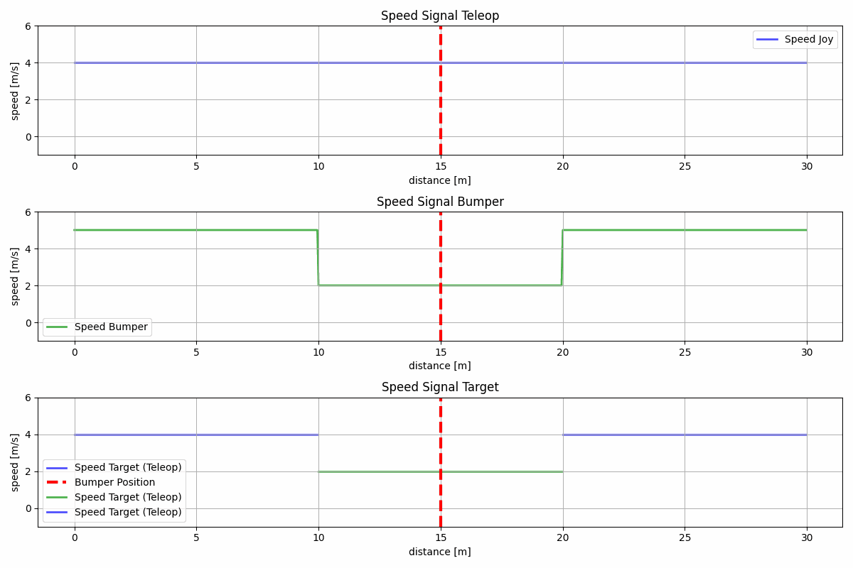
The Fig. 1 illustrates how the signal becomes saturated.
- Top graph, Joy Signal: the signal defined from the joystick control state.
- Middle graph, Bumper Signal: the signal computed by the system to limit the vehicle’s speed when crossing a bumper (safety condition).
- Bottom graph, Target Signal: the final signal resulting from combining the Joy Signal and the Bumper Signal.
Thus, the results can be interpreted as follows: before and after the bumper, the system uses the teleoperation speed; when passing over the bumper, the system saturates the speed according to the bumper-imposed limitation.
Note 1: This is the maximum speed authorized by the system, not the speed directly sent to the controller.
Others Features
The joystick can also control the turn signals and the horn of the vehicle.
- switch with 3 positions is binding on:
- IDLE (0 turn signal);
- LEFT (left turn signal);
- RIGHT (right turn signal);
- button (digital, 0 or 1) is binding on horn:
- impulsion = horn activation;
RQT
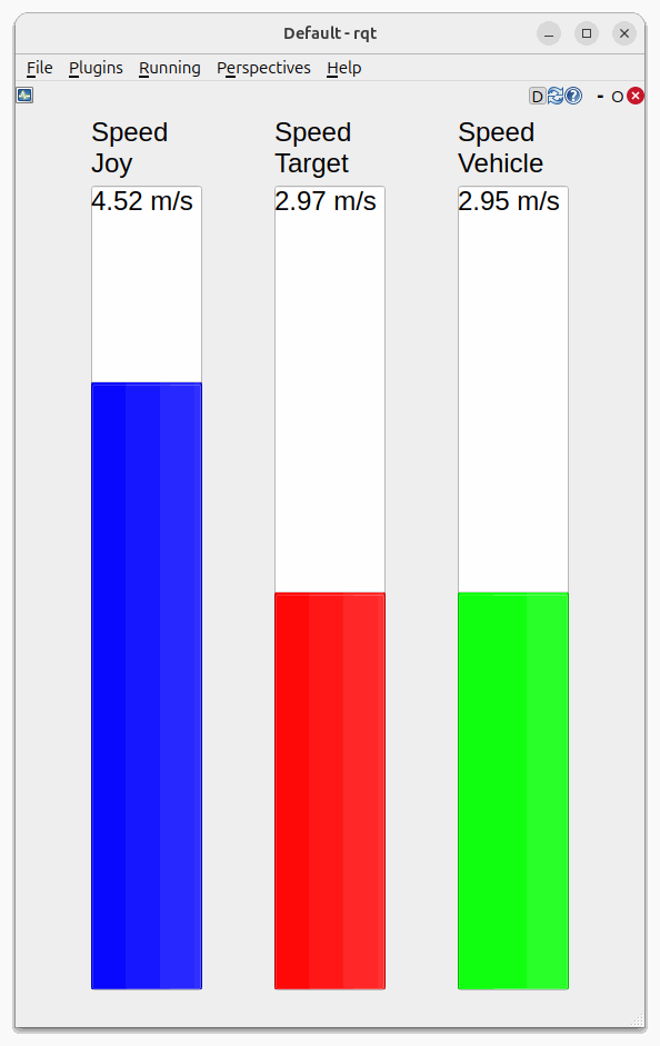
As shown in this Fig. 2 , the RQT display makes it possible to show, during operation, the different speeds (speed_joy, speed_target, speed_vehicle). This gives the user state feedback:
- the speed generated by the joystick;
- the target speed (limiting the joystick if necessary);
- the vehicle speed at time t, showing the system’s response to the target speed command.